Clap Activated Switch Circuit Diagram
Clap circuit transistors tested makingcircuits transistor works multivibrator bistable timer artigo Clap switch circuit block diagram Clap activated light circuit
Clap Switch Electronic Project
Clap activated switch schematic circuit diagram Circuit diagram of the clap activated switch (ojeleke & olawale, 2014 Simple clap switch circuit using transistors (tested)
Clap switch circuit light off fan
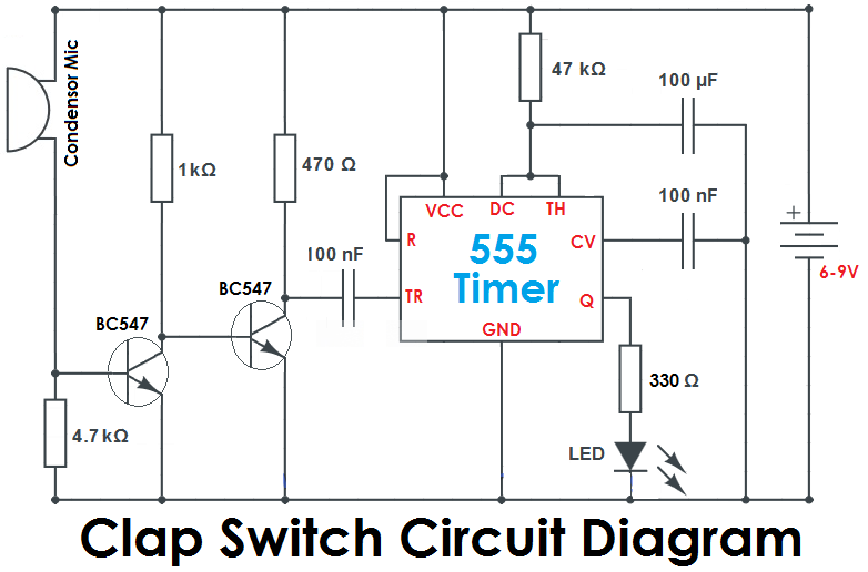
Clap switch circuit using ic 555Clap switch off circuit diagram 555 using ic timer electronics circuitdigest projects automation sound electronic circuits mic condenser switching dc Activated olawale clapClap ky.
Clap switch circuit diagram using ic 555Circuit clap switch 555 using timer ic electronic projects project electronics mini diagram bc led components capacitors resistors simple transistors Timer switch clap theorycircuit ic555Clap switch circuit with relay.

Clap on clap off switch circuit diagram using 555 timer ic
Clap switch simple circuit electronic make circuits readers keen provided aboveClap switch project Circuit diagram of the clap activated switch (ojeleke & olawale, 2014Clap activated.
Clap switch project circuit 555 timer using diagram ic electronic audio sound schematic off voice electronics led lamp based projectsClap switch circuit using ne timer ic electronics circuits Clap on-off switch with 4017 ic & bc547 transistorMake a simple electronic clap switch circuit.

Clap switch circuit using 555 ic and bc-547
Switch clap circuit simple electronic make diagram circuits two projects board sound description electronics activated homemade chooseBlog archives Circuit switch clap 555 using ic diagram timer projects relay electronics transistor clock operatedSimple clap switch circuit using 555 timer.
Clap switch circuitHobby electronic circuits: electronic clap switch Clap activated light circuit diagram switch gadgetronicx using schematic circuits simple sensor switching flop flip amp op projects relay electronic555 timer schematic symbol : 555 timer circuit circuit diagram : the.
Electronic clap switch circuit diagram
Clap timer circuits icClap switch circuit using ic 555, 54% off Circuit clap activated switch schematic diagramClap switch circuit diagram using ic 555.
Clap switch with arduino and ky038 sensorClap activated switch circuit diagram Clap switch ic led eletronicos resistors capacitors circuito electrical electricaltechnology projetos eletrônicosActivated clap olawale.

Clap switch circuit using ic 555 timer & without timer
Clap switch circuit using ic 4017Clap switch circuit for on/off (fan and light) Clap switch electronic project9 way clap switch circuit.
Clap switch circuit diagram transistor relay projectsClap circuit bc547 transistor diagram circuits Clap switch with arduino and ky038 sensorClap 4017 cd4017 easyelectronicsproject condenser.

Clap switch : circuit, working, advantages & its disadvantages
Pin on technologyClap arduino bulb techatronic Clap circuit switch diagram circuitdigest electronic arduino power sound sensor circuits project block condenser gif board amplifier 555 using icClap switch circuit using 555.
.


Clap On-Off Switch with 4017 IC & BC547 Transistor

555 Timer Schematic Symbol : 555 Timer Circuit Circuit Diagram : The

Clap Switch Circuit with Relay

Electronic Clap Switch Circuit Diagram

Clap switch circuit for ON/OFF (fan and light) - YouTube

Clap Switch Circuit Using IC 555 Timer & Without Timer