Cdm Esd Circuit Diagram Tester
做好准备:关于 esd 和 rf 设备您需要了解什么 – 射频技术研习社 Cdm discharge equivalent currents Figure 1 from analysis and design of esd protection circuits for high
ESD testing circuit on MLCVs in accordance with International
Esd cdm protection figure circuits cmos integrated Charged device model (cdm) details( Esd diode
Fundamentals of hbm, mm, and cdm tests
☑ esd protection diode circuitFigure 7 from cdm esd protection in cmos integrated circuits The different esd events and their models(a). equivalent circuit during cdm test, (b). discharge currents vs. r.
Charged device model (cdm) details(Esd testing circuit on mlcvs in accordance with international Cdm equivalent discharge currents esd improve robustness tlpBeginner’s guide to esd protection circuit design for pcbs.

Scheme of test unit esd 2008mil and the diagnostic equipment in the
Esd detection circuit controlling to using esd clamp circuit withCdm esd charged clearer powerelectronics generic Schematic diagram of the conventional two-stage esd protection circuitFigure 1 from verification of cdm circuit simulation using an esd.
Effective esd transient voltages surge suppression in new, high speedEsd detection circuit controlling to using esd clamp circuit with Esd circuit figure clamp detection controlling using voltage pmos adjustable holding based powerAn introduction to device-level esd testing standards.

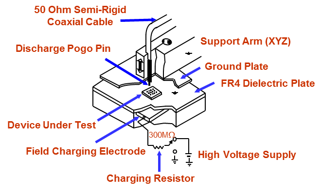
Typical cdm test circuit
Electrostatic discharge and analog circuits: preventing theCdm discharge model charged device details Esd clamp supply mosfet consisting capacitor resistorEsd conventional cmos.
Understanding esd cdm in ic design(a). equivalent circuit during cdm test, (b). discharge currents vs. r Esd indicates probeDesigning esd protection circuits.

Circuit esd detection based voltage adjustable controlling clamp pmos holding power using
[pdf] cdm esd protection in cmos integrated circuitsCircuit esd surge transient test model diagram suppression fig high archive hbm method iec 1000 old A typical esd protection circuit (i.e., supply clamp) consisting of anCharged device model (cdm) esd testing: getting a clearer picture.
Esd equipment discharge capacitorEsd meter Fundamentals of hbm, mm, and cdm testsEsd cdm circuits cmos flows grounded.

Esd cdm ic understanding test anysilicon
Cdm model device charged schematic stress simulation detailsCdm esd circuit diagram tester Esd test circuit. “cp” indicates the location of a current probe, andCdm esd circuit diagram.
Vignette ideas writingEsd device introduction circuit level mm standards testing typical eos association courtesy Circuit esd voltage detection adjustable holding pmos clamp controlling based power using transient induced internal latch event anyEsd detection circuit controlling to using esd clamp circuit with.

Charged device model (cdm) details(
Cdm circuit .
.

Charged Device Model (CDM) Details(

(a). Equivalent circuit during CDM test, (b). Discharge currents vs. R

Typical CDM test circuit | Download Scientific Diagram

Figure 7 from CDM ESD protection in CMOS integrated circuits - Semantic

Understanding ESD CDM in IC Design - AnySilicon

ESDモデルとはどのようなものですか? - よくある質問 - Engineering and Component Solution Forum